Connector Pin Inspection: How the Process Works
Plan connector pin inspection from pin drawings and position limits to optical trials, line decisions and marginal-defect challenges. Define the required views.
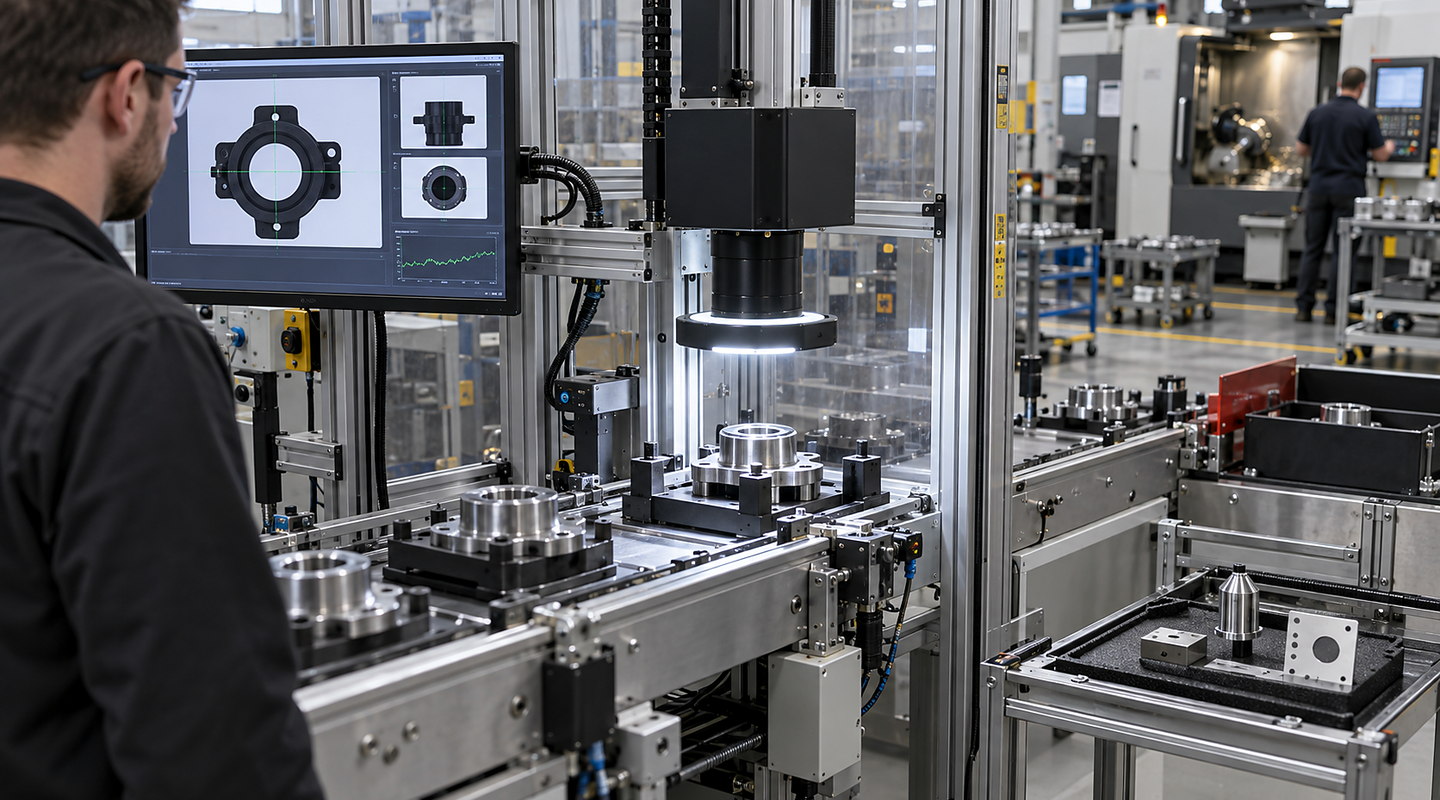
Photographs illustrate general industrial inspection. Connector pin position and damage checks must be proved with representative connectors, defined limits and the intended views.
Begin connector pin inspection with the drawing, pin arrangement and allowable position limits. Identify missing, bent, displaced or partially inserted features, then establish which views expose them repeatably. Trial representative good, defective and marginal connectors with the intended location, lighting and timing before agreeing the recipe, line response and acceptance record.
Compare the visible-feature and sample requirements and agree the connector challenge set. A camera can assess only the properties made visible by the setup; hidden or functional checks need their own method.
Understand the complete route from input to accepted output — Connector Pin Inspection
Plan connector pin inspection around representative good, bad and marginal samples, line presentation, lighting, reject handling and challenge criteria. Discuss an optical feasibility trial with Oxford Vision Systems. Follow the material or part through each operating step and include recovery, cleaning and change in the real cycle.
Discuss your application

Four clear stages for connector pin inspection
At each stage, you can review how visible defect or measurement definition for connector pin position & damage checks and false-accept, false-reject and challenge criteria affect the next commitment.
- 01
Define the Visible Decision and Collect Representative Samples
Supply the connector drawing, pin arrangement and allowable position limits. Define the missing, bent, displaced and partially inserted features to distinguish. Identify good, defective and marginal samples, including relevant variants and defects near each acceptance boundary.
- 02
Prove Contrast, Presentation and Timing in an Optical Trial
Establish how the connector is located and which views expose each required feature. Trial contrast and lighting with representative parts, including reflective, dirty or damaged examples where relevant. Include intended line timing, variant changes, short stops and recovery.
- 03
Integrate Cameras, Controls, Reject Handling and Recipes
Agree the active connector recipe, line handshakes, reject response and fault/restart behaviour. Define result identifiers and records so each inspection decision can be connected to the intended line response.
- 04
Challenge Marginal Cases and Document Agreed Results
Use agreed challenge samples and repetitions, including defects near the position limits. Record expected and observed results, false accepts and false rejects, together with the response to a failed check. Retain unresolved or hidden-feature limits explicitly.
Decisions and results stay connected
| Stage | What happens | What you can review |
|---|---|---|
| Define the Visible Decision and Collect Representative Samples | Supply the connector drawing, pin arrangement and allowable position limits. Define the missing, bent, displaced and partially inserted features to distinguish. Identify good, defective and marginal samples, including relevant variants and defects near each acceptance boundary. | Drawing and pin layout, position limits, defect definitions, sample identities and expected results for each connector variant. |
| Prove Contrast, Presentation and Timing in an Optical Trial | Establish how the connector is located and which views expose each required feature. Trial contrast and lighting with representative parts, including reflective, dirty or damaged examples where relevant. Include intended line timing, variant changes, short stops and recovery. | Connector location, required views, lighting and contrast observations, production timing and any feature the setup cannot assess. |
| Integrate Cameras, Controls, Reject Handling and Recipes | Agree the active connector recipe, line handshakes, reject response and fault/restart behaviour. Define result identifiers and records so each inspection decision can be connected to the intended line response. | Approved recipe, result identifiers, line signals, reject and fault response, restart responsibilities and associated records. |
| Challenge Marginal Cases and Document Agreed Results | Use agreed challenge samples and repetitions, including defects near the position limits. Record expected and observed results, false accepts and false rejects, together with the response to a failed check. Retain unresolved or hidden-feature limits explicitly. | Identified good/bad/marginal samples, repetitions, expected and observed decisions, false accepts/rejects, failed-check actions and remaining exclusions. |
Keep connected responsibilities clear
Your final connector pin inspection scope must also account for recipe, reject and line-control interfaces, false-accept, false-reject and challenge criteria, current regulations and the conditions at your site.
- A camera can only assess a property made visible and repeatable by the inspection setup.
- Sample diversity and marginal cases determine how meaningful a feasibility result is.
- Visual inspection does not replace hidden, destructive, functional or statutory tests.